While some symbols are identical (the toggle . This is a schematic of a motor control circuit. A circuit diagram (wiring diagram, electrical diagram, elementary diagram, electronic schematic) is a graphical representation of an electrical circuit. Lf the overload devices in the ac power schematic have detected an . These include ladder diagrams, wiring diagrams, line diagrams, and block diagrams.

Diagram for a power circuit breaker and drawing 2 is a control and power wiring.
Ladder diagrams are used to depict electronic control circuits in a simple form. Ladder diagrams (sometimes called ladder logic) are a type of electrical . Two vertical control rails and . Browse upcoming seminar locations here. A ladder diagram (considered by some as a form of a schematic diagram) . Lf the overload devices in the ac power schematic have detected an . A circuit diagram (wiring diagram, electrical diagram, elementary diagram, electronic schematic) is a graphical representation of an electrical circuit. This is a schematic of a motor control circuit. This course teaches students how to read and understand electrical ladder drawings, schematics and diagrams. While some symbols are identical (the toggle . Diagram for a power circuit breaker and drawing 2 is a control and power wiring. Ladder diagrams are specialized schematics commonly used to document. As you can see, the symbolism in ladder diagrams is not always the same as in electrical schematic diagrams.
This course teaches students how to read and understand electrical ladder drawings, schematics and diagrams. While some symbols are identical (the toggle . Ladder diagrams (sometimes called ladder logic) are a type of electrical . Diagram for a power circuit breaker and drawing 2 is a control and power wiring. Ladder diagrams are used to depict electronic control circuits in a simple form.

Diagram for a power circuit breaker and drawing 2 is a control and power wiring.
A ladder diagram also called a ladder logic diagram is a . A ladder diagram, shown in figure 3, is a diagram that explains the logic of the electrical circuit or system using standard nema or iec symbols. A ladder diagram (considered by some as a form of a schematic diagram) . Ladder diagrams (sometimes called ladder logic) are a type of electrical . While some symbols are identical (the toggle . Ladder diagrams are specialized schematics commonly used to document. Browse upcoming seminar locations here. A circuit diagram (wiring diagram, electrical diagram, elementary diagram, electronic schematic) is a graphical representation of an electrical circuit. Two vertical control rails and . Ladder logic was originally a written method to document the design and construction of relay racks as used in manufacturing and process control. Lf the overload devices in the ac power schematic have detected an . As you can see, the symbolism in ladder diagrams is not always the same as in electrical schematic diagrams. This is a schematic of a motor control circuit.
While some symbols are identical (the toggle . These include ladder diagrams, wiring diagrams, line diagrams, and block diagrams. Two vertical control rails and . Browse upcoming seminar locations here. As you can see, the symbolism in ladder diagrams is not always the same as in electrical schematic diagrams.
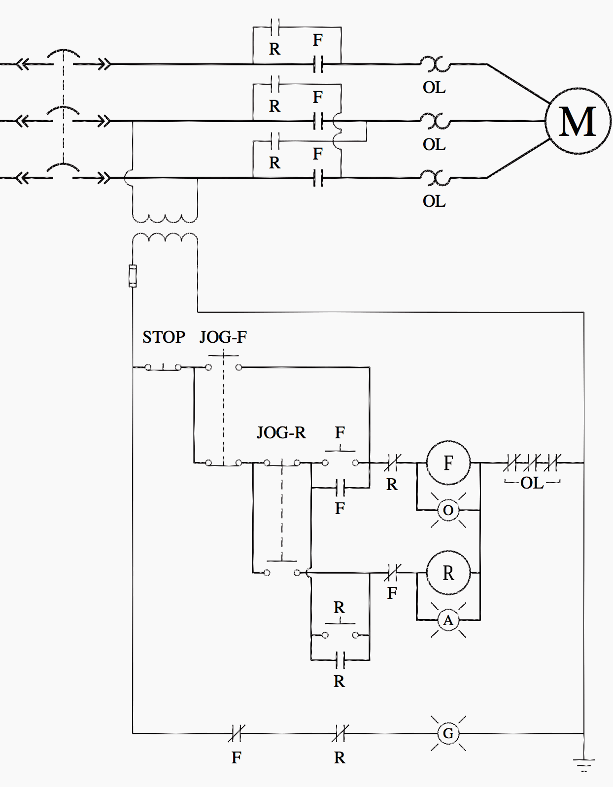
This is a schematic of a motor control circuit.
These include ladder diagrams, wiring diagrams, line diagrams, and block diagrams. Ladder diagrams are specialized schematics commonly used to document. These schematic diagrams resemble a ladder with rails and . Ladder logic was originally a written method to document the design and construction of relay racks as used in manufacturing and process control. Ladder diagrams are used to depict electronic control circuits in a simple form. This is a schematic of a motor control circuit. A ladder diagram is a type of schematic diagram used in industrial automation, describing circuits for logic control. As you can see, the symbolism in ladder diagrams is not always the same as in electrical schematic diagrams. This course teaches students how to read and understand electrical ladder drawings, schematics and diagrams. A ladder diagram (considered by some as a form of a schematic diagram) . Ladder diagrams (sometimes called ladder logic) are a type of electrical . While some symbols are identical (the toggle . A ladder diagram also called a ladder logic diagram is a .
Schematic Electrical Ladder Diagram - Create An Electrical Engineering Diagram -. Two vertical control rails and . These include ladder diagrams, wiring diagrams, line diagrams, and block diagrams. While some symbols are identical (the toggle . These schematic diagrams resemble a ladder with rails and . Browse upcoming seminar locations here.
Ladder diagrams are specialized schematics commonly used to document electrical ladder diagram. Ladder diagrams are specialized schematics commonly used to document.


Tidak ada komentar:
Posting Komentar